Gate Relay Installation
This guide covers the physical installation and wiring of Shelly Pro 1 relays used to connect NiceCheckIn terminals to gates, turnstiles, and door buzzers.
Safety Notice
Installation must be carried out only by a qualified electrician. Disconnect the power supply before starting any work and verify the circuit is de-energized.
Required Materials
| Material | Description |
|---|---|
| NiceCheckIn terminal | 1x per unit |
| Shelly Pro 1 | 1x relay per controlled output |
| Ferrules | Wire end sleeves |
| NYM-J 3x1.5 mm² cable | Or suitably dimensioned cable |
| Circuit breaker | If not already installed |
| Screwdrivers | Flathead and Phillips |
| Voltage tester | For verifying de-energized circuits |
| Wire stripper | For cable preparation |
Installation Steps
1. Preparation
- Switch off the power supply at the distribution board.
- Verify there is sufficient space to mount the Shelly relays inside the panel.
- Identify the incoming supply lines: L = Live (Phase), N = Neutral, PE = Protective Earth.
2. Connecting the Power Supply
- Connect the Live wire (L) to the L terminal of each Shelly relay.
- Connect the Neutral wire (N) to the N terminal of each Shelly relay.
- Daisy-chain the L and N connections to supply all relays with power.
3. Connecting the Control Circuits
Connect the inputs and outputs as shown in the wiring diagrams below. The exact wiring depends on whether you are installing door buzzers or gates/turnstiles.
4. Testing the Wiring
- Restore power at the distribution board.
- Use a multimeter to verify correct voltage at each relay.
- Manually activate each Shelly relay and check if the connected device responds correctly.
Configuring the Shelly Relays
Important
Assign static IP addresses for each Shelly device and make sure all relays are in the same subnet and IP range as your NiceCheckIn scanner units.
- Connect the Shelly relays to your network via ethernet (strongly recommended).
- Connect to each device using the Shelly app (iOS or Android).
- Assign a descriptive name to each relay (e.g., "Shelly 01 – Left Door").
- Configure the desired switching mode in the app.
- Enter your network credentials to connect the Shelly devices to the local Wi-Fi.
NiceCheckIn Device Settings
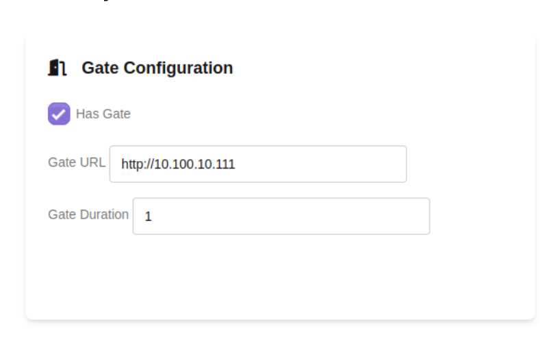
After the Shelly relays are configured on the network, link them to your NiceCheckIn terminals in the Device Management section of the Management App. Enable Has Gate and enter the relay's static IP address as the Gate URL.
| Field | Description |
|---|---|
| Has Gate | Enable gate/relay control for this terminal |
| Gate URL | The static IP address of the Shelly relay (e.g., http://10.100.10.111) |
| Gate Duration | How long the relay stays activated per trigger (in seconds) |
Wiring Diagrams
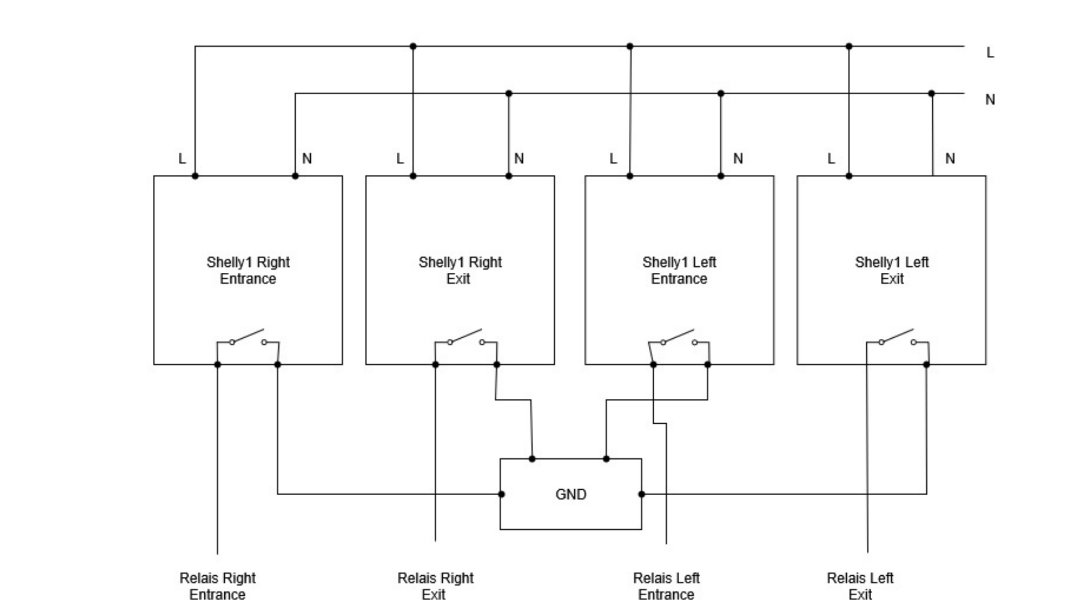
Gate / Turnstile Installation
This example shows a four-unit gate setup with entry and exit control. Each NiceCheckIn terminal operates one relay output per gate side.
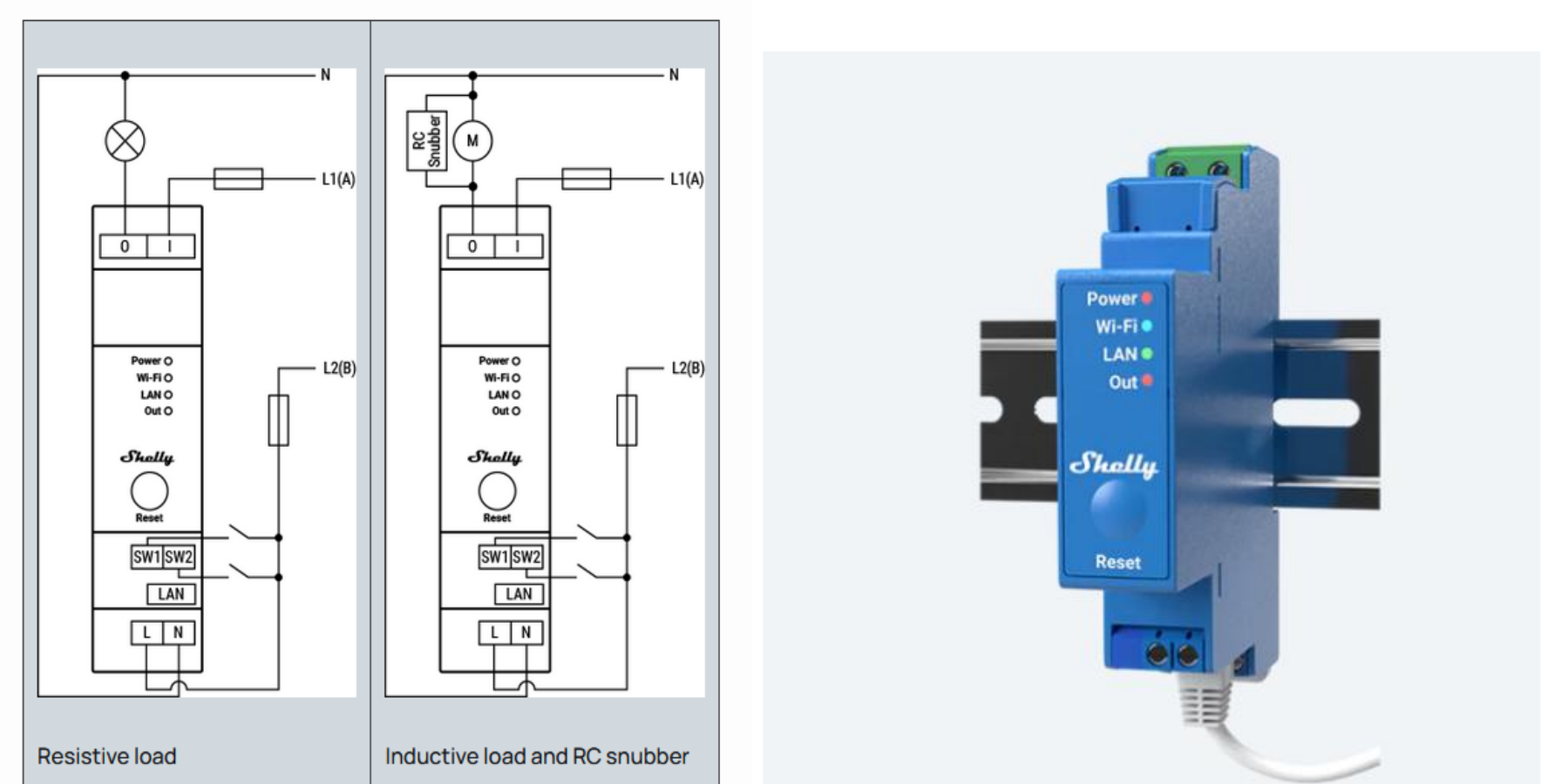
Shelly Pro 1 Wiring Reference
The diagrams below show the Shelly Pro 1 terminal connections for resistive loads (e.g., buzzers) and inductive loads with an RC snubber (e.g., motorized locks).
Door Buzzer Installation (Optional)
For setups that use door buzzers instead of gates, the wiring follows the same principle. This example demonstrates a 2-door setup with entry and exit control.
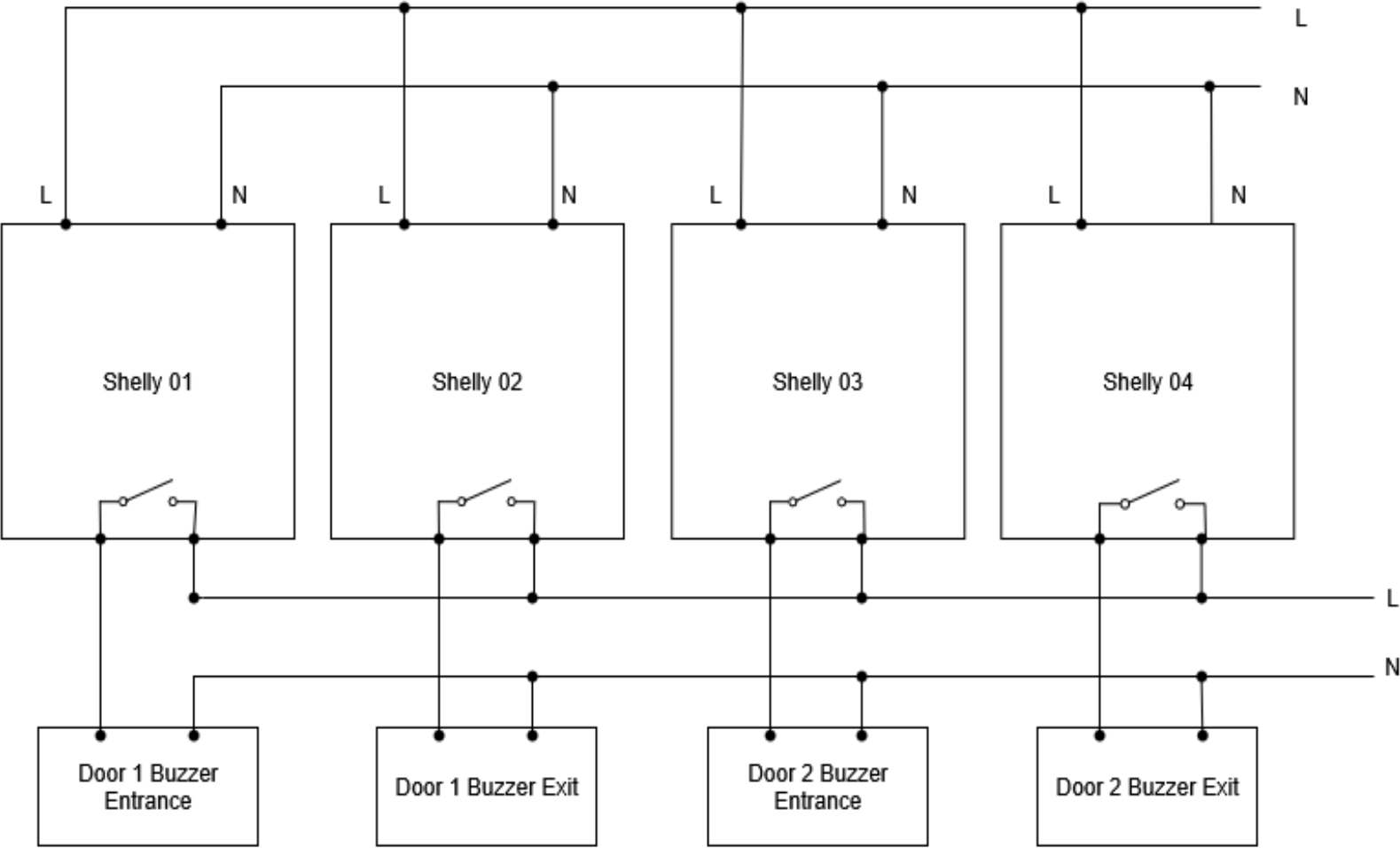
Info
If the door buzzers have dry contacts, the wiring remains the same.
Final Function Test
Before handing over the system, complete the following checks:
Test each connected load individually and confirm proper operation
Verify relay control via the Shelly app
Verify relay triggering from the NiceCheckIn terminal after a successful scan
Provide a handover briefing to the system operator on usage and troubleshooting